%20(1).png)

Author: Richard A. Milam | Organization: 5 Layers Deep | Lakeland, FL | September 2026
Concept developed with the aid of Claude (Anthropic) but concept and functional features created by Richard A Milam. Released under Creative Commons CC-BY 4.0. Build onit, critique it, improve it, take it further.
The Self-Driven Heat Conveyor (SDHC) is a proposed passive thermal-transport architecture: a closed tube loop containing a train of porous, self-lubricating slugs separated by discrete cells of a two-phase working fluid. Cells partially vaporize and expand in the heated zone; cells condense and contract in the cooled zone; wall-mounted one-way features rectify the resulting pressure oscillations into unidirectional circulation of the slug train. Because circulation is driven by rectified saturation-pressure differences rather than by buoyancy or capillarity, the device is predicted to transport heat passively in any orientation, including long horizontal runs — a capability the gravity-driven thermosyphon and the capillary heat pipe do not offer.
This paper presents the reference architecture; derives the governing selection rule for volume-constrained phase-change conveyors — the volumetric latent energy density of the saturated vapor, eᵥ = ρᵥ·h_fg; develops a first-order transport and self-sustainment model; and applies both to a reference design in saturated water at 200 °C. The reference design predicts on the order of 11 kW per 25 mm loop at 0.5 m/s train velocity and a 30 K hot-to-cold carry, scaling linearly with both. Approximately 90% of the predicted transport is sensible enthalpy advected in the liquid and slug train; phase change serves principally as the propulsion mechanism, making the device a self-pumped convection loop rather than a heat-pipe analogue.
No SDHC has been built at any scale. The paper therefore concludes with a formal ledger of open problems — six in physics and eleven in engineering, each stated with what is known, what is needed, and a suggested first experiment — and an invitation to collaborate. Three of the physics problems are survival questions whose adverse resolution would terminate the concept; all three are answerable on a transparent-tube benchtop rig running warm water at university-program cost. The concept is released under Creative Commons CC-BY 4.0 with no commercial rights retained on the architecture as described.
Self-driven heat transport — the movement of thermal energy without external power, externally supplied machinery, or operator action — is served by a short catalogue of physical mechanisms: conduction, gravity-driven natural circulation (including the two-phase thermosyphon), capillary-driven heat pipes, and the self-excited pulsating heat pipe. Each carries structural constraints. Conduction is short-range. Natural circulation requires a favorable gravity vector: the sink must sit above the source, and long horizontal runs are excluded. Capillary pumping is limited in head and degrades under acceleration. Pulsating heat pipes remain difficult to predict and are themselves orientation-sensitive in most implementations.
This paper describes a proposed additional mode: mechanically rectified phase-change advection. The Self-Driven Heat Conveyor is a closed tube loop containing a train of porous slugs separated by discrete cells of a saturated two-phase working fluid. Cells in the heated zone partially vaporize and expand; cells in the cooled zone condense and contract; wall-mounted one-way features rectify the symmetric pressure oscillations into unidirectional circulation of the entire train. The working fluid pumps itself by phase change, and because the drive is a rectified saturation-pressure difference rather than buoyancy, circulation is, to first order, independent of orientation and of the gravity vector. Gravity-independent passive heat transport is the one-sentence value proposition.
The claims of this paper are deliberately limited. No hardware exists. What is presented is: (i) a reference architecture in which each failure mode identified by first-order analysis has been met with a specific engineering response (Section 2); (ii) the governing selection rule — a design law — for any volume-constrained phase-change conveyor, which determines the fluids and temperatures at which the architecture is viable (Section 3); (iii) a first-order transport and self-sustainment model applied to a reference design in saturated water at 200 °C (Section 4, Appendix A); (iv) a positioning of the device against incumbent passive two-phase technologies (Section 5) and a survey of candidate application regimes (Section 6); and (v) a formal ledger of open problems, six in physics and eleven in engineering (Section 8). Three of the physics problems are survival questions: an adverse answer to P1 (train dynamics), P2 (thermodynamic self-sustainment), or P3 (seal blow-by) terminates the concept.
A secondary motivation is taxonomic. New modes of passive heat transport are rare, and the catalogue above has not grown in decades. If the SDHC circulates, it adds a genuinely new entry; and even absent an application, the bounded dynamics of a rectified, fluid-coupled slug train constitute a novel nonlinear system of independent academic interest.
The concept is released under Creative Commons CC-BY 4.0 with no commercial rights retained on the architecture as described, and the paper closes with a specific invitation to collaborate (Section 9).
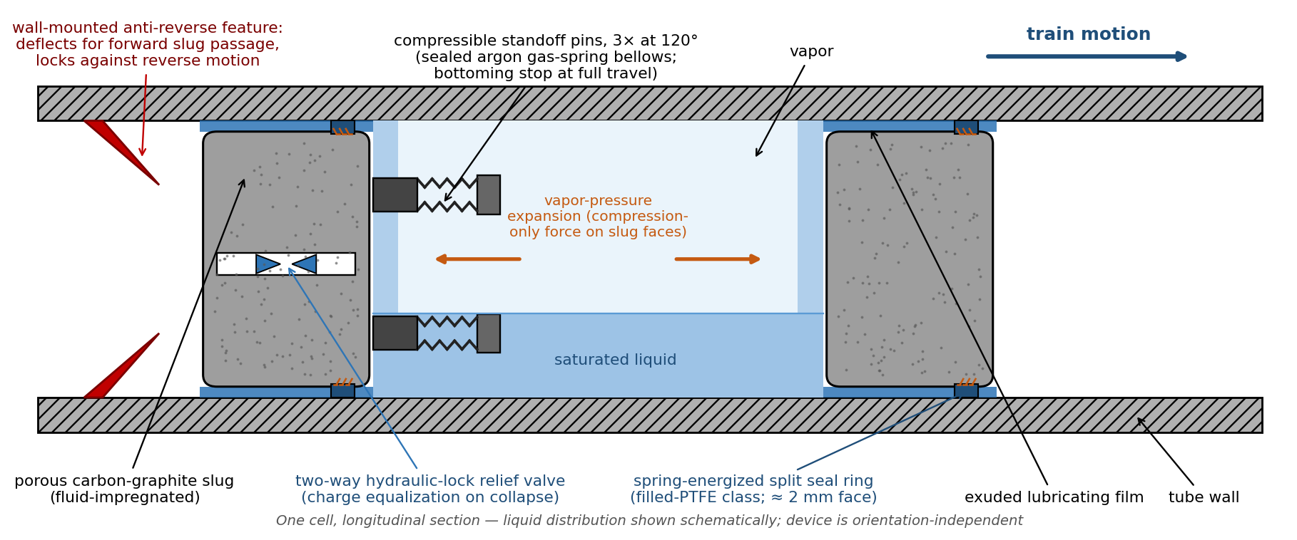
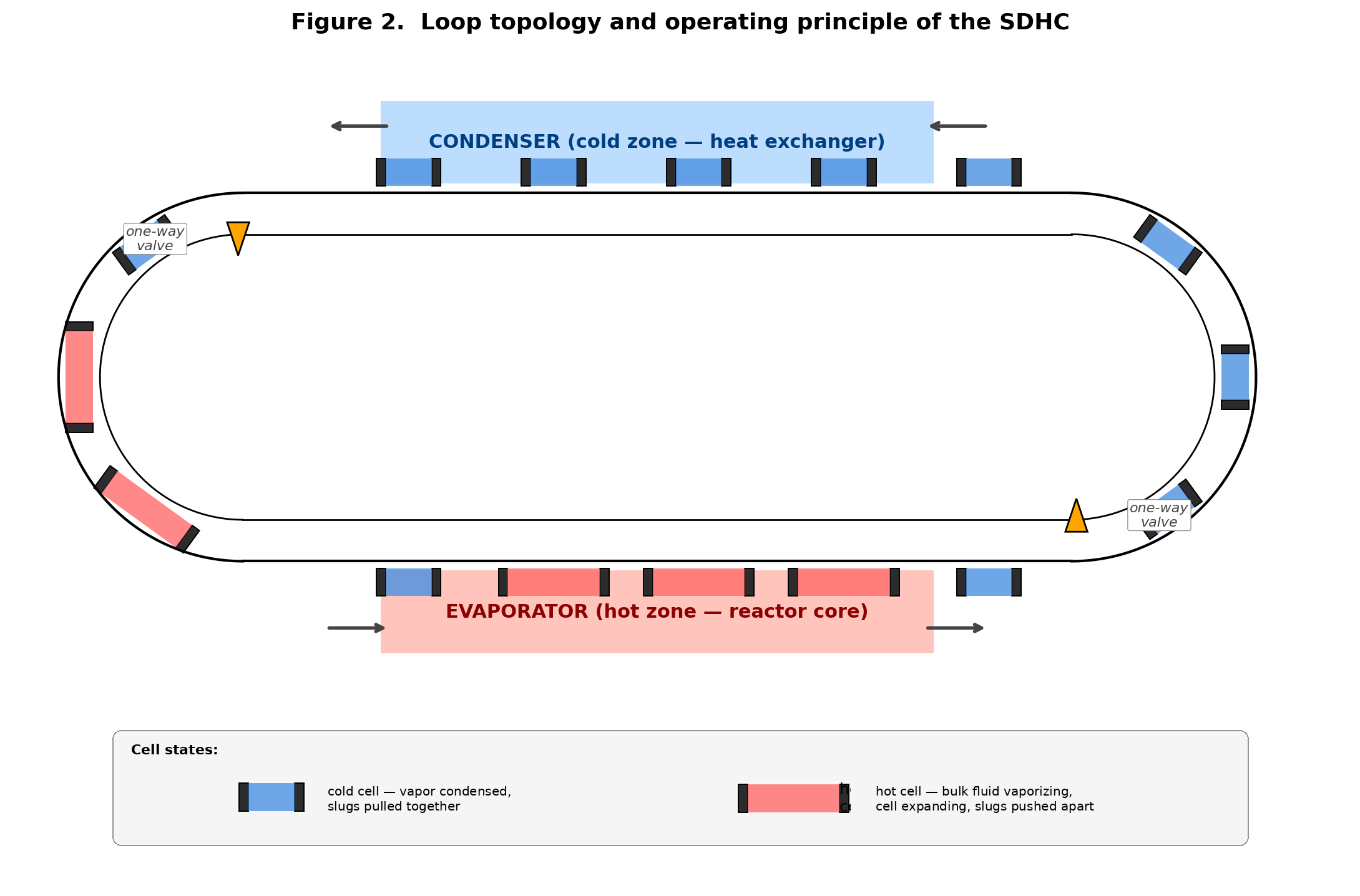
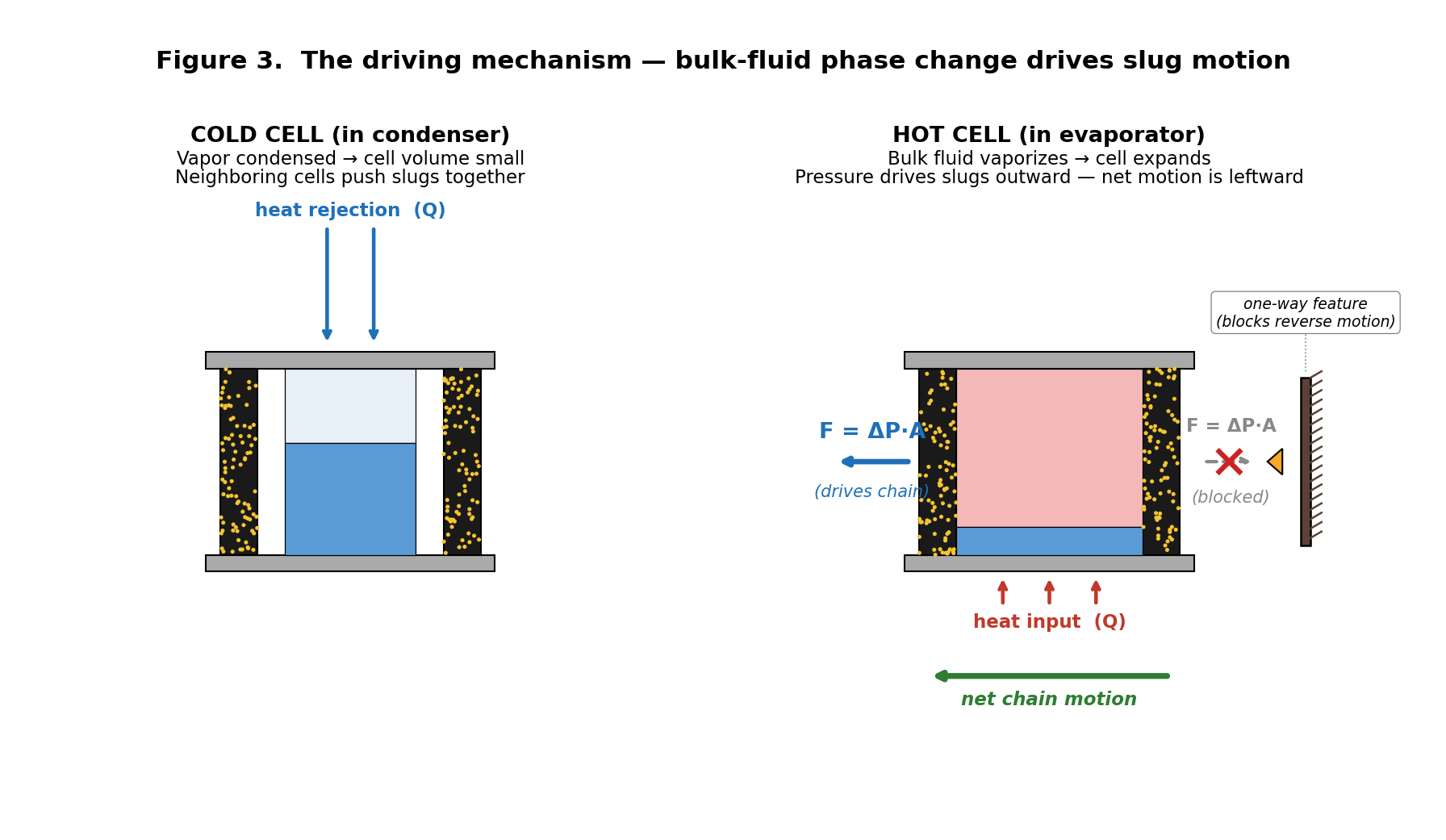
The SDHC consists of a closed loop of tubing containing a sequence of porous slugs separated by cells of working fluid. Figure 1 shows a single cell in longitudinal section, Figure 2 the closed-loop topology, and Figure 3 the driving mechanism.
Each cell contains a charge of working fluid — liquid plus vapor at saturation — bounded on each side by a porous slug. The slug body is a porous, self-lubricating material (carbon-graphite is the reference choice) impregnated with the working fluid. The pore network holds liquid in capillary suspension and exudes it slowly to the slug–wall interface as the slug slides. The exuded film lubricates the sliding contact, supplements sealing beneath the seal ring, and provides thin-film evaporation surface in the heated zone. The architecture combines the closed-loop conveyance topology of the disk-and-chain conveyor with the self-lubricating tribology of impregnated bearing races, and uses phase change of the conveyed fluid itself as the propulsion mechanism. There are no wicks, no pumps, and no valves in the working-fluid path.
There is no mechanical linkage between slugs. They are discrete free bodies, coupled through the fluid cells and constrained by the wall-mounted anti-reverse features, and a fluid coupling of this kind transmits compression only: vapor pressure acts on the slug faces, and an attempted tension simply cavitates the liquid or expands the vapor. The architecture treats compression-only transmission as a design premise and makes it deterministic through the standoff elements described next.
Each slug carries three compressible standoff pins on one face, arranged at 120° on a bolt circle (Figure 1). The reference pin is a sealed argon-charged gas-spring bellows with an internal bottoming stop at full travel; a metal coil spring is the simpler fallback. The pins give each cell a hard minimum volume with a compliant approach to it. A condensing cell collapses onto its neighbors’ pins with a spring-cushioned landing rather than an impact; at full travel the pins bottom on their internal stops and the two slugs become a positive force-transmitting unit. The collapsed cold-leg column is therefore a spring-coupled pushrod — compliant at engagement, effectively rigid under load — and hot-leg drive force transmits through it by solid contact rather than by pressure coupling.
Slug collision, liquid expulsion, and cell coalescence — the catastrophic branches of the train-stability problem — are excluded by construction, since no cell can compress below its standoffs. Over-expansion is bounded by load sharing: a cell expanding aggressively finds its neighbors already on their stops and must push the entire collapsed column, so load distributes across the train and no single cell can be crushed. The three-pin arrangement keeps the slug square under contact, leaves the cell centerline open for fluid distribution, and displaces well under 1% of the cell’s fluid volume. In addition, the rising spring force near full compression provides a restoring push toward uniform pitch, and the gas-charged variant stiffens with temperature (sealed-charge pressure rises ≈61% from 20 to 200 °C) — an adaptive property, though not one the concept depends on.
The slug–wall annulus must hold cell-to-cell pressure differentials of tens of kPa. A plain cylindrical slug cannot: capillary holdoff of the liquid film is only 1.5–6 kPa, annular blow-by scales with clearance cubed, and at a realistic 30–40 μm running clearance a cell’s drive pressure drains in 1–2 seconds — faster than one loop transit (Appendix A.9). Each slug therefore carries a spring-energized split seal ring, adapted directly from oil-free reciprocating-compressor piston-ring and rider-band practice, which has run non-metallic self-lubricated rings against dry and wet cylinders for seventy years at pressures, speeds, and cycle counts well beyond this device’s demand. The floating split ring tracks the bore across the full 20–200 °C range, removing the differential-thermal-expansion clearance problem, and brings effective sealing clearance into the ≈10 μm class where blow-by falls within budget.
The reference ring material is carbon-graphite-filled modified PTFE — the standard dry-running compressor ring compound, hydrolysis-resistant in hot water — with bearing-grade PEEK as the stiff alternate and impregnated mechanical carbon as an all-carbon alternate that also ports to a future high-temperature variant. Ring contact pressure need only modestly exceed the sealed differential (tens of kPa, versus MPa-class in compressors), so estimated ring drag is ≈0.1–0.4 N per slug — within the self-sustainment drag budget of Appendix A.8 with margin. The seal-tension-versus-drag trade is the central design tension of the machine. The porous slug body behind the ring retains its original duties: lubricant exudation and regenerator mass.
The standoff pins define a geometric setpoint for the correct liquid charge: fill is sized so that at full collapse the liquid just fills the minimum cell volume. An overcharged cell then cannot reach its stops — the incompressible liquid locks first, and column force drives the trapped-liquid pressure well above anything normal operation produces. A small two-way relief valve in each slug, set to crack at 2–3× the maximum operating differential, opens only under that hydraulic lock and passes the excess liquid to the neighboring cell. Every condenser transit thereby becomes a metering event: charge distribution converges toward the geometric setpoint automatically, and the chronic consequence of residual ring blow-by — slow inventory migration between cells over months and years — is reset every circuit rather than accumulating toward flooded and dried-out cells. Hydraulic lock is converted from a failure mode into the sensing mechanism.
The same feature transforms assembly: per-cell charging tolerance is eliminated as a requirement, because the loop can be bulk-charged approximately and left to distribute its own inventory over the first dozen warm transits (Problem E6). A magnetically actuated variant — an external magnet opening the valves at a fixed station past the condenser — trades the passive pressure trigger for external controllability and is retained as the instrumented-rig configuration rather than the reference design.
Expansion pushes both bounding slugs symmetrically; without rectification the train would oscillate in place rather than circulate. Wall-mounted anti-reverse features — the reference concept is a compliant reed or pawl that deflects for forward slug passage and locks against reverse motion (Figure 1) — convert the symmetric pressure swings into unidirectional circulation. They are the architecture’s single most important functional element and its least-developed component (Problem E1): every result in this paper assumes they work. A consequence of the standoff architecture is a defined shutdown state: on cooldown every cell condenses and collapses onto its pins, and the train parks as a column of known length against the anti-reverse features, so every startup begins from one deterministic configuration.
In the heated zone a small fraction of each cell’s liquid vaporizes; the large liquid-to-vapor volume ratio converts that small mass fraction into a large volume expansion, pushing the bounding slugs. In the cooled zone the reverse occurs, and the rectified pressure differential between expanding and contracting cells drives circulation. In the moderate-temperature regimes where the device is viable (Section 3), however, the latent heat carried by the vapor is a minor fraction of total transport: most of the heat rides as sensible enthalpy in the circulating liquid and in the slug bodies, which function as a moving regenerator, absorbing heat in the heated zone and releasing it in the cooled zone. The correct model of the device is a self-pumped convection loop whose pump is distributed phase change.
For a sealed loop of fixed internal volume, vaporized fluid must exist as vapor somewhere inside the loop. The latent energy resident in the device at any instant is therefore bounded by the vapor space multiplied by the volumetric latent energy density of the saturated vapor,
and the latent energy advected per unit time is eᵥ multiplied by the volumetric flow of vapor space through any cross-section (Appendix A.1). No design parameter internal to the loop — fill fraction, cell count, slug geometry, buffer gas — appears in this prefactor. It is set entirely by the choice of working fluid and saturation temperature, and it varies by nearly three orders of magnitude across common engineering choices. Figure 4 maps it. This selection rule governs the SDHC and, the author suggests, any sealed slug-train or discrete-cell phase-change conveyor; no prior published statement of it is known to the author.
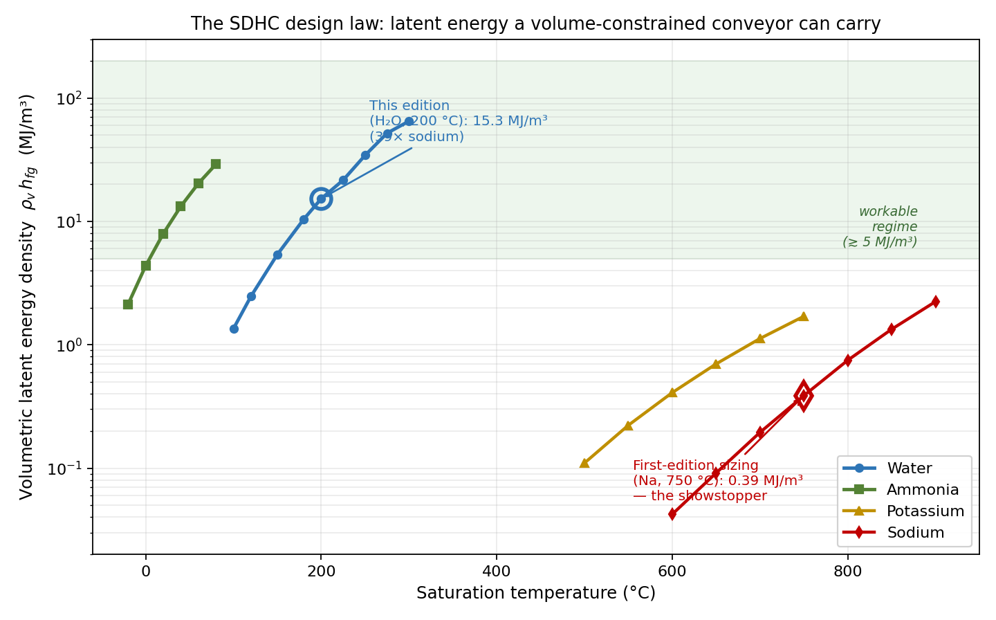
Representative values: sodium at 750 °C, 0.39 MJ/m³; water at 200 °C, 15.3 MJ/m³; water at 250 °C, 34 MJ/m³; ammonia, 2–29 MJ/m³ across −20 to 80 °C. The practical rule of thumb is that the architecture requires a working fluid at moderate reduced pressure, approximately eᵥ ≳ 5 MJ/m³ — for water, saturation temperatures above about 150 °C. Ammonia is the natural fluid for low-temperature and aerospace regimes. The alkali metals reach workable territory only near or above 900 °C: a very high-temperature version of this architecture may exist, but it is not the near-term path.
Within their respective windows, water and ammonia are not merely acceptable choices but close to optimal ones, because each wins both terms of the transport equation of Section 3.1. Water carries the highest latent heat of vaporization of any common working fluid (1.94 MJ/kg at 200 °C), which powers the propulsion term, and an anomalously high liquid heat capacity (4.50 kJ/kg·K, the highest of common liquids), which powers the sensible term that carries most of the duty — a pairing no organic or refrigerant approaches, since those fluids run roughly half the liquid heat capacity and a quarter of the latent heat. Water is also non-toxic, non-flammable, chemically simple against steel and carbon, and free. Ammonia repeats the pattern in the low-temperature window: latent heat of 1.1–1.3 MJ/kg and liquid heat capacity near 4.7 kJ/kg·K, which is why it is the standard spacecraft two-phase working fluid. The fluid selections of this paper are therefore not conveniences; they are near the optimum the selection rule admits.
The consequences of ignoring this parameter are severe, and a worked counterexample is instructive. Sodium at 750 °C — a common heat-pipe operating point — sits at a saturation pressure of only ≈27 kPa; its vapor density is ≈0.10 kg/m³ and eᵥ ≈ 0.39 MJ/m³. For the reference loop geometry of Section 4, the entire vapor space at that point holds roughly 380 J of latent energy in transit at any instant, and latent advection at practical train velocities delivers on the order of 10 W — not the tens of kilowatts a heat-pipe replacement would require. Reducing fill fraction, substituting NaK, or adding a buffer gas does not change the conclusion, because none of these raises the partial density of the working vapor. An early sizing study of this device by the author, anchored at exactly that operating point, failed an independent first-principles audit by roughly three orders of magnitude for this reason. The architecture was not at fault; the operating point was among the least favorable in common engineering practice.
The full transport model follows from the advected enthalpy difference between the hot and cold legs. With tube cross-section A, train velocity v, net vapor void-fraction differential Δα between hot-leg and cold-leg cells, hot-to-cold carry temperature difference ΔT, and loop length fractions f_liq and f_slug occupied by liquid and slug material:
The three terms are latent advection, liquid sensible advection, and the slug-train regenerator. In the moderate-temperature water regime the second term dominates: water’s liquid heat capacity is large enough that the advected liquid carries roughly an order of magnitude more heat than the vapor. This is the reframing stated in Section 2.7 — the vapor’s job is propulsion. On that job the selection rule pays twice, because the available driving pressure swing (a fraction of P_sat) rises with the same reduced pressure that raises eᵥ: at 200 °C water, a 10% saturation-pressure swing exerts 56 N per cell front on the reference tube section, against estimated drag forces of 0.1–0.4 N per slug. Propulsion authority and transport capacity improve together.
Derivations, property sources, and the per-cell energy accounting appear in Appendix A. Every input to the model — Δα, ΔT, v, and the regenerator utilization — is stated as an assumption and flagged as challengeable; Problems P5 and P6 in Section 8 request that these assumptions be replaced with derived or measured values.
The reference geometry is a 12-foot, 1-inch-OD out-and-back closed loop with 85 cells — a representative single-tube passive-transport envelope of heat-pipe class. Nothing about the architecture requires this geometry; duty scales with tube area and train velocity. All assumptions are stated in the tables and are inputs to be challenged, not conclusions.
The reference geometry is a 12-foot, 1-inch-OD out-and-back closed loop with 85 cells — a representative single-tube passive-transport envelope of heat-pipe class. Nothing about the architecture requires this geometry; duty scales with tube area and train velocity. All assumptions are stated in the tables and are inputs to be challenged, not conclusions.
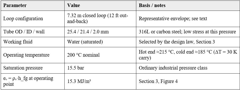
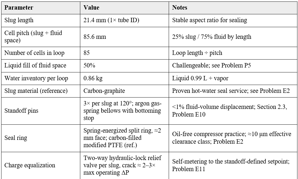
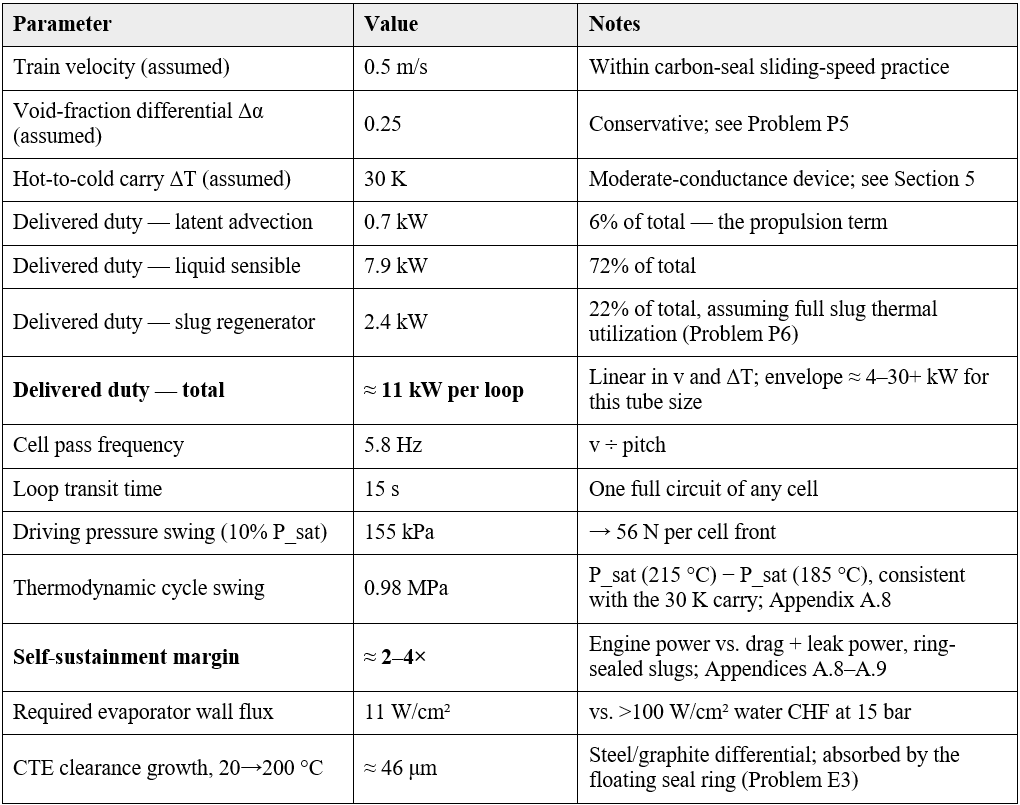
Three observations follow. First, the sizing closes with margin: the latent-inventory ceiling of Section 3 sits above the sensible-dominated duty, the required evaporator wall flux is an order of magnitude below the pool-boiling critical heat flux at this pressure, and available drive force exceeds estimated drag by more than two orders of magnitude. Second, the duty is modest: this is a kilowatt-class to tens-of-kilowatt-class transporter per 25 mm loop, and candidate applications should be selected accordingly rather than stretched to fit. Third, the two assumed inputs most in need of replacement by measurement are Δα and the slug regenerator utilization (Problems P5 and P6); the total duty claim is best read as “order 10 kW, with the sensible terms robust and the latent term uncertain but small.”
The thermal interfaces of the reference design are conventional and deliberately zoned. The evaporator and condenser sections receive full-perimeter (circumferential) heating and cooling — the sizing of A.5 already assumes it — and every other part of the loop, the adiabatic transport legs and turnarounds, is insulated: heat lost through a transport-leg wall is delivered duty lost, and premature condensation in the hot column erodes the drive differential before it reaches the condenser. Insulation also defines the zone boundaries sharply, which Section 7’s capacity-control property exploits. Because the internal side carries an order-of-magnitude flux margin (11 W/cm² required against >100 W/cm² critical heat flux), the external film coefficient is always the bottleneck: bare tube suffices for liquid or condensing external media, and standard finned-tube practice applies wherever the external medium is a gas — an air-cooled condenser would be finned as a matter of course.
Because roughly 90% of the predicted transport is sensible and the device operates with a finite carry ΔT, the appropriate comparison class is the two-phase thermosyphon, not the near-isothermal wicked heat pipe. Both the thermosyphon and the SDHC are passive, wickless, moderate-conductance devices. The SDHC’s distinguishing claim against that class is specific: a thermosyphon requires gravity — condenser above evaporator, continuous elevation gain, no long horizontal runs — and the SDHC does not, because circulation is driven by rectified saturation-pressure swings rather than by buoyancy.
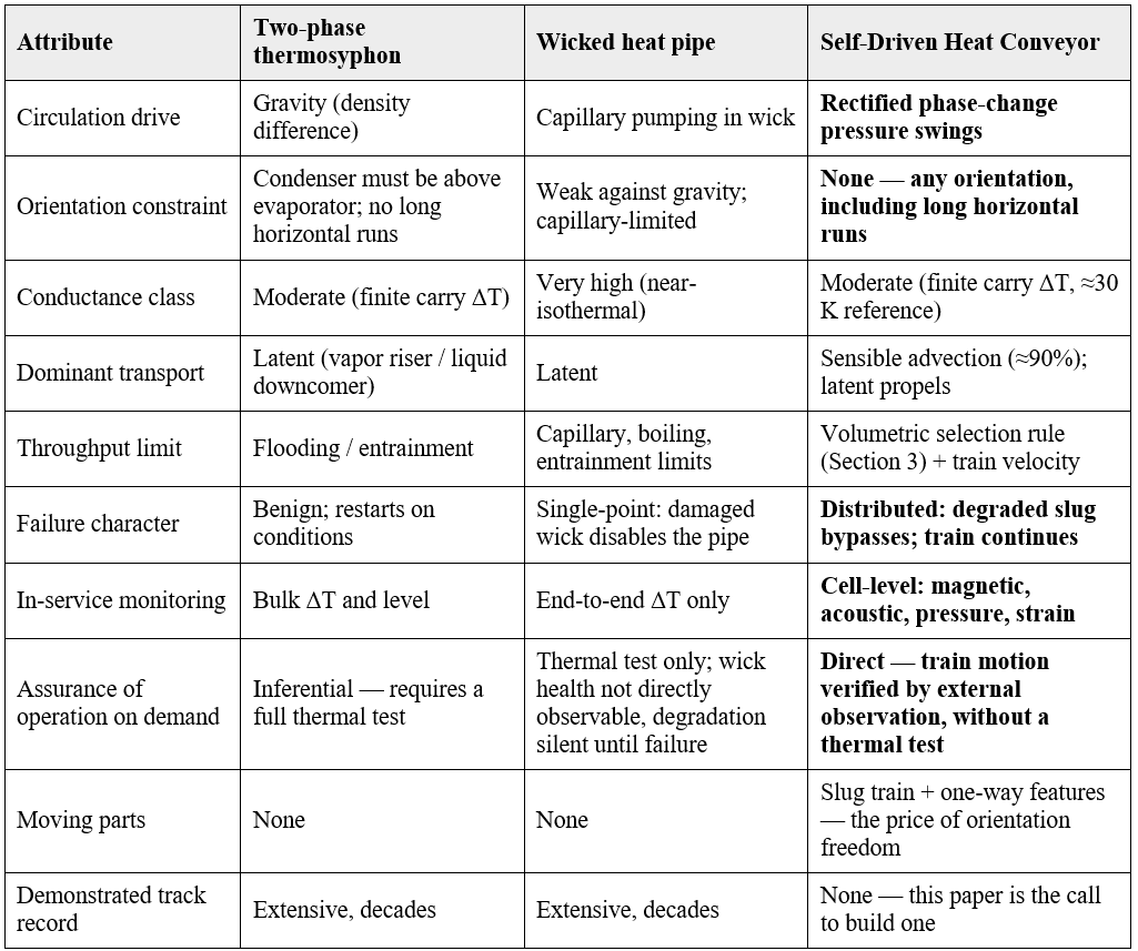
Two rows of the table weigh against the SDHC and are stated without mitigation. The device has moving parts, which no thermosyphon or heat pipe has; that is the price paid for orientation freedom, and it is why the tribology and valve problems of Section 8 are survival questions rather than refinements. And it has no demonstrated track record at any scale. A reader deciding whether the architecture deserves effort should weigh exactly this trade: mechanical complexity and unproven dynamics, in exchange for a capability — passive horizontal transport with cell-level observability — that the incumbent passive devices structurally cannot offer.
This paper commits to no single application. The concept is released openly so that others can find the fit — or the flaw — that the author cannot. Three regimes in which the differentiators plausibly command a premium are sketched to orient that search. They share two features: pumped loops are disqualified (no power, no maintenance, or no reliability credit for active systems), and geometry or motion disqualifies gravity-driven devices.
This is the regime the reference sizing serves directly. Passive decay-heat removal systems must move hundreds of kilowatts to a few megawatts from core or vessel to an ultimate heat sink with no power and no operator action, and plant geometry rarely cooperates with thermosyphon routing: heat sinks are not always overhead, and containment penetrations force horizontal runs. A 45 MWth small reactor generates roughly 585 kW of decay heat one hour after shutdown — about 50 loops of the reference size at the design point, and materially fewer at the ≈100 K carry ΔT such an application would have available. Two structural features favor this regime: standby duty reduces the one-way-feature lifetime cycle count from ~10⁹ (continuous operation) to ~10⁷ (surveillance testing plus events), retiring the hardest reliability demand by application choice; and the cell-level monitoring of Section 7 addresses the operability-demonstration question that every standby safety system must answer for a regulator, by direct observation rather than inference.
Directed-energy systems, high-power avionics, and radar on maneuvering platforms require kilowatt-class transport from source to a remote heat exchanger through an airframe whose orientation and acceleration change continuously. Capillary devices lose pumping head under g-load; thermosyphons fail outright; pumped loops cost power, weight, and reliability budget. Ammonia or a refrigerant working fluid places the selection rule in workable territory across −20 to 80 °C, and the mechanically clocked train is, to first order, indifferent to the g-vector. The stability question P1 acquires a g-load dimension in this regime and must be answered for it specifically.
Process plants routinely reject usable heat because moving it 50–200 m horizontally to a point of use requires a pumped loop — capital, controls, parasitic power, and a maintenance item — that the recovered heat does not justify. A passive device moving tens of kilowatts per tube horizontally at zero operating cost changes that economics. Saturated water at 120–200 °C fits the selection rule; freeze protection (Problem E5) is the regime’s primary engineering caveat for outdoor routing.
Six properties follow from the architecture itself rather than from any particular sizing.
This section is the paper’s purpose. Each problem is stated in a fixed format — what it is, what is known, what is needed, and a suggested first experiment — so that a reader can select one and begin. The physics problems gate the engineering problems, and the first three are survival questions: an adverse answer to P1, P2, or P3 terminates the concept, and the author would rather know. Nearly every entry is answerable on a transparent-tube benchtop rig running warm water with instrumented slugs — a university-scale program measured in tens of thousands of dollars, not an alkali-metal facility.
Problem. With the standoff architecture, the catastrophic branches of the stability problem — slug collision, liquid expulsion, cell coalescence, single-cell crush — are excluded by construction: no cell can compress below its pins, and over-expansion is bounded by collapsed-column load sharing (Section 2.3). What remains is the bounded-dynamics question: how does the expansion wave organize itself around the loop? Candidate behaviors include smooth circulation, stop-engagement chatter (softened but not eliminated by the spring pins), standing or traveling compression waves in the cold column, and limit-cycle surging. The system is a chain of damped masses coupled by nonlinear two-phase springs, each with a compliant-then-rigid lower bound and asymmetric wall constraints — a well-posed and, to the author’s knowledge, unstudied nonlinear dynamics problem.
Known. The bounds themselves, by construction. The pulsating-heat-pipe literature shows that unbounded fluid-coupled slug systems readily become chaotic; the SDHC’s stops, spring compliance, porous-slug damping, and anti-reverse rectification are engineered stabilizers whose collective sufficiency for smooth circulation is unproven. The spring pins add a restoring force toward uniform pitch on the compression side.
Needed. A stability and limit-cycle analysis of the bounded train about the circulating steady state; the operating envelope in (heat flux, velocity, fill fraction, spring rate) space; characterization of the residual chatter and surge modes and their amplitudes.
First experiment. A 10–15-cell transparent loop (borosilicate or polycarbonate) with water at 60–95 °C, magnet-tagged slugs with printed spring standoffs, and external Hall sensors logging every slug position at >100 Hz. Perturb one cell thermally and measure pitch-variance response and stop-engagement statistics. This one rig also serves P2, P4, P5, E1, and E10.
Problem. Each cell traverses a heat-engine cycle: expansion at hot-leg saturation pressure, contraction at cold-leg saturation pressure. Circulation is self-sustaining only if engine power exceeds drag power plus leak power. Appendix A.8 derives the criterion and evaluates it to first order; the open problem is validation and refinement.
Known. The first-order result: the cycle pressure swing consistent with the 30 K carry is 0.98 MPa, delivering 26–44 W of pumping power at the design point — a total train drag budget of 53–88 N, or 0.6–1.0 N per slug, against estimated ring drag of 0.1–0.4 N per slug. Nominal margin ≈ 2–4×. The rectangular-cycle idealization, the assumed Δα, and the drag estimates are all first-order.
Needed. The real cycle shape (P-V trajectory with finite-rate heat transfer and rectification losses), the stall threshold at low flux, the operating curve (velocity versus applied power — which is also the control map for the variable-exposure throttle of Section 7), and measured — not estimated — ring drag.
First experiment. Same rig as P1: measure steady train velocity versus applied evaporator power, map the operating curve including the stall point, and compare against the A.8 prediction. A towed-slug drag measurement calibrates the budget side of the inequality.
Problem. Blow-by past a slug short-circuits the pressure differential that drives the train. Appendix A.9 computes the bound: capillary holdoff of the liquid film is only 1.5–6 kPa against cell-to-cell steps of tens of kPa, and annular Poiseuille leakage scales with clearance cubed — at a plain slug’s 30–40 μm running clearance, a cell’s drive pressure drains in 1–2 seconds, faster than a loop transit. The plain slug fails on paper; the spring-energized seal ring of Section 2.4 is the architectural response, bringing effective clearance to the ≈10 μm class where per-slug leakage falls to ≈0.1–0.2 mL/s, inside the ≈20%-of-displacement budget.
Known. The bound, the cubic scaling, the budget, and the compressor-industry precedent. Unknown: real leakage of a split ring in this geometry (ring-joint gap, groove side-sealing), two-phase film behavior under the ring, and pore-exudation replenishment of the lubricating film under wall heating.
Needed. Measured blow-by versus ΔP, temperature, and velocity for the reference ring in the reference bore; ring-joint leakage characterization; confirmation that residual leakage stays inside the self-sustainment budget of A.8 across the operating envelope.
First experiment. A single ringed slug in an instrumented tube section: apply controlled ΔP across it at temperature and measure leak flow directly, static and towed. Bench hardware, days not months — and the single most important measurement this paper requests.
Problem. From rest, with all cells at uniform temperature, does asymmetric heating spontaneously start circulation, and what is the threshold heat flux? The one-way features select the direction, but the bifurcation from static to circulating has not been analyzed.
Known. The qualitative mechanism is clear — the first heated cell expands, is rectified, and displaces the train — and the loop has no gravity dependence to overcome. The standoff architecture removes initial-condition uncertainty: shutdown parks the train in the all-collapsed configuration against the anti-reverse features, so every start begins from one deterministic state. Threshold flux, transient duration, and any failure-to-start modes from that state are unknown.
Needed. The startup criterion as a function of applied flux, fill fraction, and initial train configuration; identification of any locked configurations from which the train cannot start.
First experiment. Same rig as P1: repeated cold starts from the parked all-collapsed state across a range of applied powers; log start/no-start and time-to-circulation, and verify that the park state is in fact reached on every cooldown.
Problem. The latent-transport multiplier and the drive amplitude both depend on how much more vapor a hot-leg cell holds than a cold-leg cell. The reference sizing assumes Δα = 0.25. In reality Δα is set by cell residence time, wall heat transfer, the volume constraint, and the pressure-rectification dynamics — a solvable coupled problem that has not been solved.
Known. Bounding is straightforward (0 < Δα < the fluid fraction); the actual value and its dependence on velocity and flux are not known even to first order.
Needed. A per-cell transient thermal model coupled to the train kinematics, validated against measured void fractions.
First experiment. Transparent-loop void imaging: high-speed video through the tube wall at matched hot-leg and cold-leg stations, giving direct Δα measurement versus power and velocity.
Problem. The reference sizing credits the slug train with full thermal utilization — every slug cycling its entire heat capacity between hot-end and cold-end temperatures every circuit. Real utilization is set by transient conduction into the slug body over a 15 s circuit time and will be lower; the 22% regenerator contribution is therefore an upper bound.
Known. The slug Biot and Fourier numbers at the reference point indicate partial utilization is likely for monolithic graphite; radially graded or high-diffusivity slug designs could recover it. An electromagnetically aligned anisotropic-graphite slug (high radial, low axial conductivity) is a directly relevant design option.
Needed. Conjugate transient analysis of a moving 50%-full cell with a conducting slug; regenerator effectiveness versus circuit time and slug design.
First experiment. Thermocouple-instrumented slugs in the P1 rig: measure actual slug temperature swing per circuit versus the ideal.
Problem. The least-developed component in the architecture. The features must rectify train motion, pass slugs with low drag, hold ~155 kPa reverse ΔP, and survive the lifetime cycle count with zero maintenance.
Known. Nothing beyond concept sketches. The lifetime cycle count is application-selected: ~2×10⁷ for standby decay-heat duty (surveillance plus events) versus ~10⁹ for continuous industrial duty — the standby application retires the hardest version of this problem by choice.
Needed. At least two candidate geometries (a passive flap or reed against a seat; an asymmetric-drag geometry with no moving element) carried to concept design, drag measurement, and cycle testing. A speculative third path worth one examination: integrating the anti-reverse function into the standoff architecture itself — a pin or slug feature engaging a wall detent asymmetrically — collapsing two components into one.
First experiment. Prototype both candidates in the P1 rig; measure forward drag and reverse holding, then run accelerated cycle testing of the survivor.
Problem. With the ring architecture adopted, this problem is not “characterize unknown tribology” but “adapt a solved component to a new geometry.” Oil-free reciprocating-compressor rings and rider bands (Burckhardt/Howden/API-618 practice) have run non-metallic self-lubricated split rings for seventy years at PV values, pressures, and cycle counts well beyond this device’s demand. The SDHC duty is gentle by those standards: ≈0.03–0.1 MPa contact pressure, PV ≈ 0.05–0.15 MPa·m/s, in clean hot water.
Known. Reference material: carbon-graphite-filled modified PTFE (the standard dry-running compressor compound; hydrolysis-resistant). Stiff alternate: bearing-grade PEEK (carbon/PTFE/graphite blend). All-carbon alternate: resin-impregnated mechanical carbon split rings and die-formed flexible graphite — not brittle in ring form, and the only options that port to a future high-temperature variant. Deliberate exclusion: polyimide (Vespel-class), which hydrolyzes in pressurized hot water despite excellent dry credentials — a documented trap. Virgin PTFE is excluded for creep. Open: wear rate over life in this specific plug-in-bore geometry — 8 years of continuous duty is ≈1.3×10⁸ m of sliding, at the edge of compressor ring-life practice, while standby decay-heat duty is two orders of magnitude inside it.
Needed. Friction and wear characterization of the three candidates in the reference bore versus load, speed, and temperature; measured ring drag feeding the P2 budget; projected clearance growth over life feeding the P3 margin.
First experiment. A plug-in-tube tribometer campaign in pressurized hot water — conventional tribology-lab work, anchored against compressor-industry reference data.
Problem. Differential thermal expansion between a graphite slug and a steel bore grows running clearance by ≈46 μm across 20–200 °C, against a ≈10 μm sealing requirement. The floating spring-energized split ring resolves this by construction — the ring tracks the bore at every temperature — leaving detail design rather than physics.
Known. Compressor ring-groove practice covers most of it. Residuals: groove side-clearance and side-sealing across the range, slug-body-to-bore running clearance behind the ring (loose — the ring seals, the body guides), and ring-joint gap growth from cold to hot.
Needed. Ring and groove dimensioning across 20–200 °C with the joint-gap budget tied into P3’s leakage measurement.
First experiment. Folded into the P3 single-slug leak rig: run the leak measurement across the full temperature range.
Problem. Rigid slugs of length ≈ 1× ID constrain the loop-end bend radius (R ≳ 1.5× ID from the binding estimate, ≈ 32 mm minimum for the reference tube), and the bends are also the natural location for the one-way features. No turnaround has been designed.
Known. The geometric estimate only. Articulated or segmented slugs would relax the constraint at a tribological cost.
Needed. A dimensioned turnaround design with slug transit kinematics, integrated one-way features, and — for the decay-heat application — header manifolding for multi-loop banks.
First experiment. CAD plus 3D-printed transparent turnaround sections on the P1 rig.
Problem. Water expands ~9% on freezing. A loop that can see sub-zero temperatures is an envelope-rupture risk — the water regime’s principal materials caveat.
Known. In-containment nuclear routing never sees frost and is unaffected. Outdoor industrial and aerospace routing must engineer for it.
Needed. The standard menu, selected per application: antifreeze working mixtures (with the selection-rule penalty computed), trace heating at vulnerable sections, compliant inserts absorbing expansion per cell, or drain-down provisions.
First experiment. A deliberate freeze test of a single charged cell with and without a compliant insert — destructive, inexpensive, and definitive.
Problem. How 85 slugs are loaded into a closed loop, 0.86 kg of water is charged, and the final closure is made — the loop-level manufacturability question.
Known. The relief-valve self-metering of Section 2.5 transforms the problem: per-cell charge tolerance no longer exists as a requirement. Candidate approach: load slug assemblies through an open final segment, bulk-charge the total inventory to loop-level accuracy, orbital-weld the closure, then run the loop warm and let the hydraulic-lock valves distribute the inventory to the standoff-defined setpoint over the first dozen transits. The sequence has not been demonstrated.
Needed. A documented assembly sequence demonstrated on the benchtop rig, including verification that per-cell charge converges within tolerance.
First experiment. First performed on the P1 rig by necessity — building the rig answers it.
Problem. The 15–40 bar envelope is low stress in ordinary tube, but safety-grade nuclear service means ASME Section III classification, and the slugs and one-way features are internals of a code pressure boundary.
Known. Nothing beyond the observation. The monitoring architecture (Section 7) is an asset for the operability-demonstration burden that safety classification carries.
Needed. A one-time regulatory-pathway study: classification, in-service inspection approach, and how cell-level monitoring maps onto surveillance requirements.
First experiment. Desk study with a nuclear code consultant — no hardware.
Problem. Water, graphite, and steel in a sealed loop for decades: dissolved-oxygen control, galvanic and crevice effects at the slug–wall interface, graphite oxidation kinetics at 200 °C, and radiolysis for any near-core nuclear routing.
Known. Each is an individually well-characterized system in the power industry; the combination in this geometry is not.
Needed. A coupon and materials-compatibility program under representative chemistry; a water-chemistry specification for the sealed charge.
First experiment. Sealed autoclave coupon exposures — standard corrosion-lab work, run in parallel with everything else.
Problem. The sensing concepts of Section 7 must become an engineered system: sensor count and placement, detection thresholds for the failure modes of interest, data architecture, and — for standby safety duty — a self-test protocol that demonstrates operability without a full thermal test.
Known. Every sensing modality is individually mature. The budget — which failure modes are detectable at what confidence with how many sensors — has not been constructed.
Needed. A detection-budget analysis against the failure-mode set (stalled slug, bypass leak, inventory loss, valve degradation), then a reference sensor-suite specification.
First experiment. The P1 rig’s instrumentation is the prototype of exactly this system; develop the detection algorithms against its data.
Problem. The compressible standoff pin is a new component: a sealed argon gas-spring bellows (reference) or metal coil spring (fallback), three per slug, with an internal bottoming stop at full travel. It must survive one engagement cycle per loop transit for the service life, sealed, in hot water.
Known. Engagement rate is one cycle per ~15 s transit: ≈ 1.7×10⁷ cycles over 8 years of continuous duty, and far fewer in standby decay-heat service — demanding but inside established welded-bellows fatigue practice. The gas charge stiffens ≈61% from 20 to 200 °C (sealed-volume pressure rise), which is adaptive rather than problematic. The coil-spring fallback eliminates the seal-life question at the cost of temperature-adaptive stiffness.
Needed. A pin specification: free length, travel, spring rate and preload versus the drive-force spectrum; bellows fatigue and creep life at temperature; helium-leak acceptance criteria for the argon charge; cap-face wear pairing against the neighboring slug face.
First experiment. Printed and machined pin prototypes on the P1 rig for engagement statistics, then a dedicated bellows-pin fatigue rig — a solenoid cycling one pin at accelerated rate in hot water — for life demonstration.
Problem. The charge-equalization valve of Section 2.5: a small two-way relief element in each slug that must stay sealed below crack pressure, crack reliably at 2–3× the maximum operating differential under hydraulic lock, pass liquid quickly enough to complete metering within a condenser dwell, and reseat clean — for the service life, unmaintained.
Known. The discrimination physics is strongly favorable: hydraulic lock generates pressures far above anything in normal operation, so the setpoint sits in a wide dead band. The valve is a leak path only if its seat leaks below crack — seat leakage adds directly to the P3 blow-by budget and must be counted there. Opposed spring-loaded check elements or a single preloaded shuttle are the obvious embodiments; none has been designed.
Needed. A valve specification: crack pressure and tolerance, flow capacity at crack, seat-leakage allocation within the A.9 budget, cycle life (one potential actuation per transit worst-case, far fewer once the loop has equalized), and materials for hot-water service.
First experiment. Prototype in the P1 rig with deliberately mis-charged cells: verify convergence of the charge distribution over successive transits, and measure seat leakage before and after cycling. The magnet-actuated rig variant makes this test externally controllable.
This concept is released under CC-BY 4.0 with no commercial rights retained on the architecture as described, because the work it needs exceeds what any single inventor can supply. The invitation is specific:
Correspondence: Richard A. Milam, 5 Layers Deep LLC, Lakeland, Florida, rick_milam@msn.com.
Derivative works, critiques, and experimental results are welcome under the CC-BY attribution terms.
-----------------------------------------------------
This appendix was developed with machine assistance (Claude, Anthropic). It is independently checkable and the reader is asked to check it. Property values are standard saturation-table data (IAPWS-consistent for water; Fink & Leibowitz correlations for sodium).
For a sealed loop of fixed internal volume V_loop, vapor can exist only in the vapor space V_vap = V_loop · f_fluid · (1 − fill). The latent energy resident in the loop at any instant is bounded by E_res = ρᵥ h_fg V_vap, and latent energy is advected at Q_lat = ρᵥ h_fg · A v Δα, where Δα is the void-fraction differential between hot and cold legs expressed as a fraction of tube cross-section. Both expressions carry the same prefactor eᵥ = ρᵥ h_fg; no internal design parameter appears in it. This is the selection rule of Section 3.
Reference values of eᵥ (MJ/m³): sodium 750 °C — 0.39 (P_sat ≈ 27 kPa, ρᵥ ≈ 0.10 kg/m³, h_fg ≈ 3.87 MJ/kg). Water: 150 °C — 5.4; 200 °C — 15.3 (P_sat = 1.555 MPa, ρᵥ = 7.86 kg/m³, h_fg = 1.941 MJ/kg); 250 °C — 34.3. Ammonia: −20 °C — 2.1; 20 °C — 7.9; 60 °C — 20.3.
Reference loop: A = 3.60 cm², L_loop = 7.32 m, V_loop = 2.63 L; f_slug = 0.25, f_fluid = 0.75, fill = 0.50, so V_vap = V_liq = 0.99 L across 85 cells (11.6 mL vapor space per cell). At the sodium 750 °C point the per-cell resident latent energy is 0.39 MJ/m³ × 11.6 mL ≈ 4.5 J — and fully vaporizing a cell’s 8.6 g liquid charge would require ≈ 86 L of vapor volume, about 33× the volume of the entire loop, which is why any sizing that assumes full per-cell vaporization is physically inadmissible in a volume-constrained device. At the water 200 °C point the same 11.6 mL holds ≈ 177 J — still modest, which is why the transport of Section 4 is sensible-dominated and why the duty claim rests on the advection model of A.3 rather than on per-cell latent inventory.
Q = A v [ ρᵥ h_fg Δα + ρ_l c_p,l ΔT f_liq + ρ_s c_s ΔT f_slug · η_reg ]. The three terms are latent advection, liquid sensible advection, and the slug regenerator with utilization η_reg (taken as 1.0 in the reference sizing; an upper bound — Problem P6). At the design point (water 200 °C, v = 0.5 m/s, Δα = 0.25, ΔT = 30 K, ρ_l = 864.7 kg/m³, c_p,l = 4.50 kJ/kg·K, ρ_s = 1800 kg/m³, c_s = 1.0 kJ/kg·K): Q_lat = 0.69 kW, Q_liq = 7.87 kW, Q_slug = 2.43 kW; total 10.99 kW. Sensitivities are exactly linear in v and ΔT; Δα moves only the (small) latent term.
A saturation-pressure swing of fraction ε exerts F = ε P_sat A per cell front. At ε = 0.10: water 200 °C — 155 kPa × 3.60 cm² = 56 N; for comparison, sodium at 750 °C at its corrected P_sat ≈ 27 kPa yields ≈ 1.0 N. Aggregate drive across the hot-leg cell population exceeds analog drag estimates by more than two orders of magnitude; the definitive drag number is Problem P2/P3 territory.
Evaporator taken as 40% of one leg: A_evap = π · D_ID · 1.46 m = 984 cm². Required flux at 11 kW: 11.2 W/cm². Pool-boiling critical heat flux for saturated water at 15.5 bar exceeds 100 W/cm² (Zuber), and the slug-deposited film adds thin-film evaporation in parallel; the wall is not the constraint anywhere in the envelope of Section 4.
Loop thermal mass 20 → 200 °C: water 0.86 kg × 4.3 kJ/kg·K × 180 K ≈ 0.67 MJ; slugs ≈ 1.2 kg graphite × 1.0 × 180 ≈ 0.21 MJ; envelope ≈ 8.4 kg steel × 0.50 × 180 ≈ 0.76 MJ. Total ≈ 1.6 MJ ≈ 0.46 kWh per loop before losses — supplied by the process itself in the decay-heat application, or by trivially sized trace heating for pre-test conditioning.
The standoff architecture introduces one global constraint. The loop length is fixed, so expansion anywhere requires compression somewhere; if every cold cell were already at minimum length, the train would kinematically lock. The design rule: the sum of minimum cell lengths plus the working expansion stroke of the hot leg must remain comfortably less than the loop’s available fluid length at all operating states, including the worst-case cold transient — equivalently, a guaranteed compliance reserve ΔL_res = L_fluid − [ n · L_standoff,min + Σ hot-leg expansion strokes ] > 0 with margin.
At the reference geometry the inequality is satisfied with large headroom: nominal fluid gap per cell is 64.2 mm against a bottomed standoff length of order 3–6 mm, so the cold column can absorb the entire hot-leg working stroke many times over, and the distributed spring travel (three pins per slug at ≈3 mm travel) adds a further ≈ 0.7 m of compliant reserve around the loop before any pin bottoms. The gas-spring pins make the reserve self-reporting: as the train approaches lock, spring forces rise loop-wide and train velocity falls measurably before any kinematic limit is reached — a gradual, observable approach rather than a cliff. The rule matters at the design margins — overcharged loops, low-fill configurations, or cold transients that condense the inventory rapidly — and should be verified for any geometry departing from the reference. Pin volume displacement (3 pins × ≈3 mm OD × 6 mm) is ≈ 0.13 mL per cell against 23.2 mL of fluid space: under 1%, negligible in the transport model.
Each cell traverses a heat-engine cycle: vapor generation at hot-leg saturation pressure, condensation at cold-leg saturation pressure. Idealized as a rectangular P-V cycle, engine power equals the cycle pressure swing times the volumetric displacement rate: W_engine = ΔP_cycle · A v Δα. The swing consistent with the 30 K carry is ΔP_cycle = P_sat(215 °C) − P_sat(185 °C) = 2.104 − 1.123 = 0.98 MPa — far more generous than the conservative 10% swing used for the force estimates of A.4. At the design point: W_engine = 26 W (Δα = 0.15) to 44 W (Δα = 0.25).
Self-sustainment requires engine power to exceed drag power plus leak power:
ΔP_cycle · ( V̇_displacement − V̇_blowby ) > F_drag · v
The budget side: 26–44 W of engine power at v = 0.5 m/s buys a total train drag allowance of 53–88 N, i.e. 0.6–1.0 N per slug across 85 slugs. Even the ultra-conservative floor — a 10% pressure swing — sustains 0.17 N per slug. Against it: viscous film drag is millinewtons per slug (negligible); estimated seal-ring drag at 0.03–0.1 MPa contact pressure with wet filled-PTFE friction coefficients is ≈0.1–0.4 N per slug; anti-reverse passage drag is a small intermittent addition. Nominal self-sustainment margin: ≈ 2–4×. The rectangular-cycle idealization, Δα, and the drag estimates are first-order values that Problem P2’s rig measurements are intended to replace. The stall threshold — the minimum applied flux sustaining circulation — follows from the same inequality as the flux at which ΔP_cycle collapses toward the drag floor.
Capillary holdoff of a liquid-filled annular gap is 2σ/δ: at σ = 0.030 N/m (water, 200 °C), only 1.5 kPa at δ = 40 μm and 6 kPa at 10 μm — negligible against cell-to-cell pressure steps of 30–100 kPa. The film is displaced and the gap flows. Annular Poiseuille leakage per slug, Q = π D δ³ ΔP / (12 μ L_slug), scales with clearance cubed:
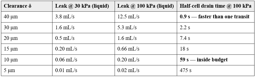
(Liquid viscosity 1.34×10⁻⁴ Pa·s; once the gap clears to vapor, leakage worsens ≈ 8× on the viscosity ratio.) The engine’s displacement flow is 27–45 mL/s total; budgeting blow-by at ≤ 20% of displacement allows ≈ 0.1 mL/s per slug — requiring effective sealing clearance in the ≈10 μm class. A plain cylindrical slug at realistic 30–40 μm running clearance therefore fails on paper: cell drive pressure drains in 1–2 seconds and circulation never establishes. The spring-energized split seal ring of Section 2.4 is the architectural response, with residual ring-joint and seat leakage (including the E11 relief valve’s sub-crack seat leakage) counted against the same 20% budget. This bound, and its experimental confirmation or refutation on a single ringed slug, is the most important measurement this paper requests (Problem P3).